


Can You Run a 12V Brushless DC Motor on 9V?
Yes, a 12V brushless DC motor may run from a 9V supply, but that does not mean every 12V BLDC system will start, carry its intended load, or operate reliably at 9V.
The deciding factors are not the motor label alone. You also need to check the motor driver or controller, the current capability of the 9V source, the load at startup, and the speed or torque the application must maintain. If the controller accepts 9V and the source can supply enough current, the motor will usually run at a lower maximum speed. If the controller reaches its undervoltage threshold or the supply voltage collapses during startup, the system may not start at all.
In EURARI's documented no-load comparison, the sample ran at 7,068 rpm with the regulated supply displaying 12.01V and 0.027A, then at 5,278 rpm with the supply displaying 9.01V and 0.024A. These are sample results under one test setup, not universal 12V or 9V ratings.
The short version is:
- Lower voltage alone does not usually burn a BLDC motor.
- A 9V rectangular battery is not the same as a regulated 9V power supply.
- Torque does not simply fall by 25% because voltage fell from 12V to 9V.
- The driver may shut down even when the motor windings could otherwise turn.
- The only safe final answer comes from the motor, driver, supply, and load as one system.
Start by defining what "12V BLDC motor" means
A brushed DC motor can be connected directly to a DC source. A BLDC motor needs electronic commutation, so a controller must switch current through its windings in the correct sequence.
That controller may be:
- an external driver connected to a three-phase motor;
- built into the motor or fan assembly; or
- part of the customer's main control board.
This distinction matters because a motor winding does not have an undervoltage lockout threshold, but the electronics driving it often do. Below the driver's operating threshold, undervoltage lockout can disable the outputs and perform a controlled shutdown.
Before trying 9V, identify both specifications:
- the motor's nominal voltage and winding data;
- the driver's allowed input-voltage range and undervoltage behavior.
If a product page lists only "12V" without identifying the controller, do not assume that 9V is approved.
Integrated-driver motors need a separate answer
A two-wire BLDC fan, pump, or motor assembly may look like a simple DC load, but its housing contains the commutation electronics. You cannot evaluate that product from the winding voltage alone. The internal controller has its own minimum operating voltage, startup threshold, current limit, and fault behavior.
Some integrated products can continue running below the voltage required to start them. Others shut down cleanly as soon as the input reaches the undervoltage threshold. For this product class, check two values in the supplier data:
- minimum startup voltage under the real load;
- minimum continuous operating voltage after startup.
Those two values are rarely published, which is why a 9V question so often ends without an answer. EURARI measured both on the two 12V EC2035012 units used for this article:
| Measured threshold (no load) | Result |
|---|---|
| Minimum startup voltage, from standstill | 7.09 V |
| Minimum voltage to keep running, reduced in 0.01 V steps until stop | 6.08 V |
| Cold starts at 9V, 10 attempts per unit | 10 of 10 on both units |
The gap between those two figures is the point. This motor needed about 7.09 V to break away from standstill, but once turning it kept running down to about 6.08 V — roughly one volt lower. A product that survives a brief supply dip while running can still refuse to start from the same voltage.
Both values were measured at no load, so they are a floor, not a specification for a loaded application. Under a real load the startup threshold rises, because the motor must produce breakaway torque against friction, gearing, or fluid pressure at the moment the driver comes out of lockout. At 9V and no load this sample had roughly 27% margin above its startup threshold, which is why all twenty cold-start attempts succeeded. That margin shrinks as soon as a load is attached.
If a supplier does not publish these two values, a 9V test must remain an engineering evaluation. It is not an approved operating condition.
What changes when the supply falls from 12V to 9V?
1. Maximum speed usually falls
As a BLDC motor spins, it generates back electromotive force, or back-EMF. The driver must apply enough voltage to overcome that back-EMF plus the voltage drops in the windings and power electronics.
Reducing the supply from 12V to 9V leaves less voltage available as speed rises. Under the same control method and a light load, the no-load speed will often fall roughly with the available motor voltage. However, treating 9V as exactly 75% of the 12V speed is only a first estimate. Driver voltage drops, PWM strategy, current limits, winding resistance, commutation timing, and the load all change the result.
A useful steady-state approximation is:
ω ≈ (Vmotor − I × R) / Ke
Here, Vmotor is the effective voltage applied to the motor, I × R is the winding voltage drop, and Ke is the back-EMF constant. Near no load, current is relatively low, so the I × R term becomes smaller. If the controller behaves the same at both voltages, the quick estimate becomes:
n9V ≈ n12V × 9 / 12
EURARI publishes a 7,000 rpm no-load speed for its 12V EC2035012. Applying the simple voltage ratio gives:
7,000 × 9 / 12 = 5,250 rpm
EURARI then documented the same no-load sample at two supply settings. At 12.01V and 0.027A, the stroboscope measured 7,068 rpm. At 9.01V and 0.024A, it measured 5,278 rpm.
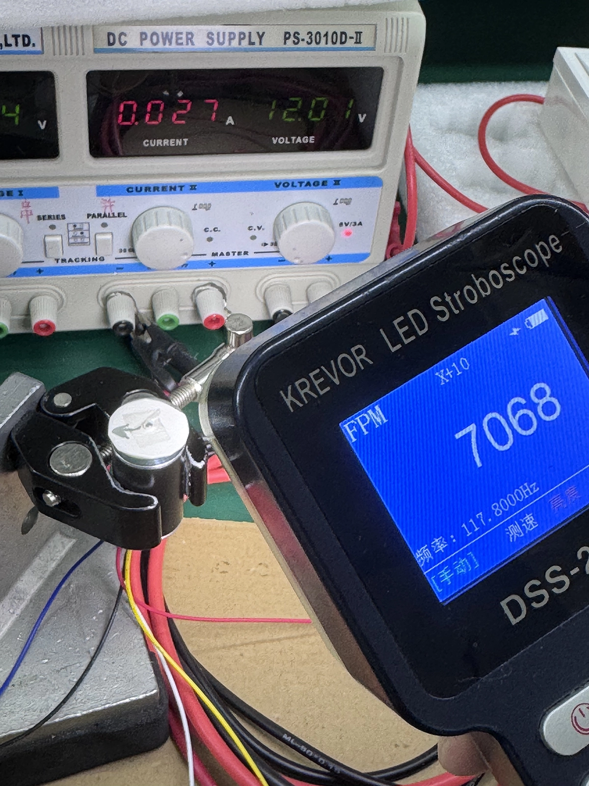
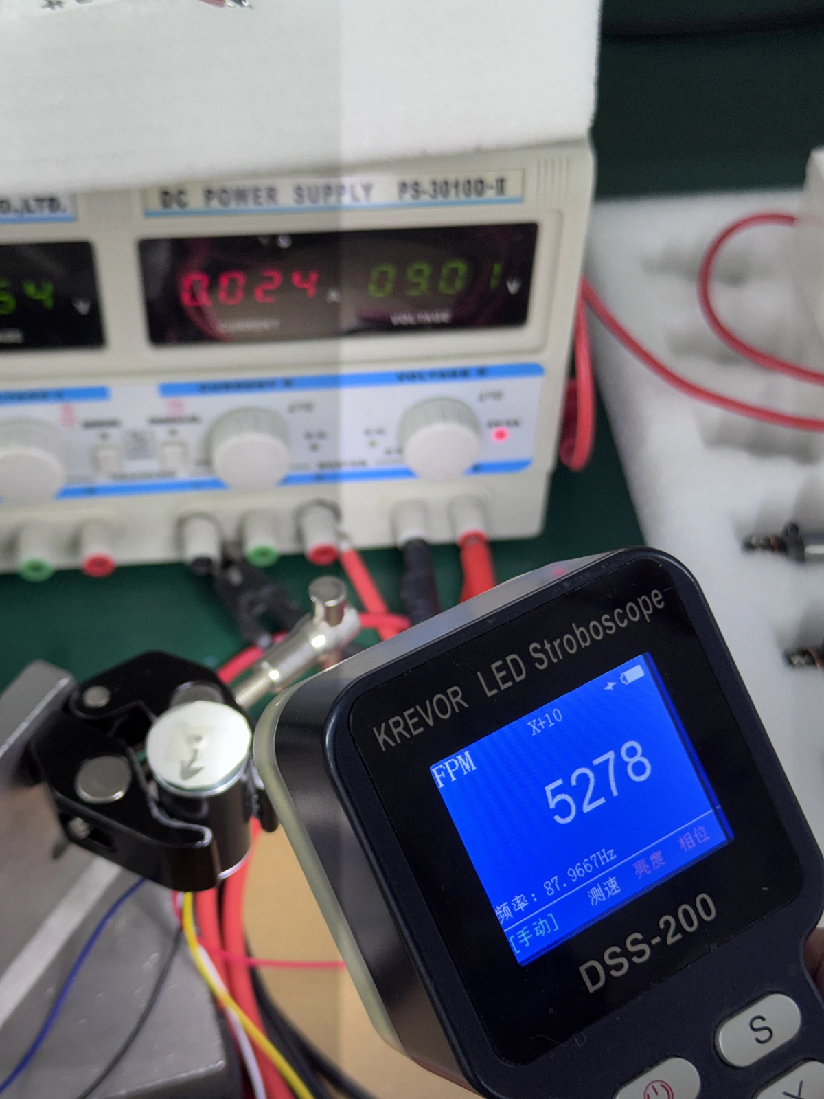
The measured 9V speed was 28 rpm above the 5,250 rpm estimate, a difference of about 0.5%. The measured speed ratio, 5,278 / 7,068, was about 74.7%, while the measured voltage ratio, 9.01 / 12.01, was about 75.0%. The displayed no-load current also changed from 0.027A to 0.024A, so it did not increase at 9V in this test. This close result supports the voltage-ratio estimate for this sample at no load. It does not predict loaded current or guarantee the same result under load, or with a different driver.
A second unit gave nearly the same result
One sample proves very little about a product line, so a second EC2035012 unit was measured under the same conditions:
| Unit | At 12.01 V | At 9.01 V |
|---|---|---|
| Unit 1 | 7,088 rpm | 5,288 rpm |
| Unit 2 | 7,068 rpm | 5,278 rpm |
| Difference | 0.3% | 0.2% |
Two units are still a small sample, not a production capability study. But the agreement means the speed ratio described above is not an artifact of one unusually well-behaved motor, and it gives a sense of how much unit-to-unit spread to expect before designing a margin around a single measurement.
Why the ratio worked: the speed constant did not move
The voltage ratio is not a coincidence. It follows from the approximation above, and the same two measurements can be used to check it.
Dividing each measured speed by its measured supply voltage gives an effective speed constant for this sample:
| Supply | Measured speed | Effective speed constant |
|---|---|---|
| 12.01 V | 7,068 rpm | 589 rpm/V |
| 9.01 V | 5,278 rpm | 586 rpm/V |
The two values differ by about 0.5%. That is the practical meaning of Ke being a motor constant: it is set by the magnetic design and the winding, not by the supply voltage. Because it did not move between the two tests, no-load speed tracked the supply almost proportionally.
This is a supply-terminal figure, so it includes the drops inside the integrated driver and is not the winding-terminal back-EMF constant. It also holds near no load, where the I × R term is small. Under load, current rises, the I × R term grows, and measured speed falls below the simple ratio.
Test conditions
Two EC2035012 units, plain shaft, no load, clamped in a bench fixture. Regulated DC supply, model PS-3010D-II, channel II. Speed measured with a KREVOR DSS-200 LED stroboscope. Ambient temperature [ambient °C], tested [test date]. Readings are taken from the supply display and the stroboscope display, not from a calibrated reference instrument.
For a speed-critical application, measure the actual operating point instead of relying on the ratio alone.
2. Torque does not fall in direct proportion to voltage
This is where many explanations go wrong. Motor torque is primarily related to winding current and the motor's torque constant. Supply voltage determines whether the driver has enough voltage headroom to build and regulate that current, especially as speed and back-EMF rise.
At low speed, a suitable current-controlled driver may still deliver the current needed for the load at 9V. At higher speed, the lower supply can prevent the driver from maintaining that current, so the available torque drops sooner along the speed-torque curve.
In practical terms:
- a light-load motor may run normally, only slower;
- a constant-torque load may demand nearly the same current as before;
- a heavy-starting load may fail to accelerate;
- a fan or blower load may become much lighter as speed falls.
There is no universal "25% less voltage equals 25% less torque" rule.
3. Maximum mechanical power is usually lower
Mechanical power depends on both torque and speed. Even if the motor can produce the required low-speed torque, its lower speed ceiling reduces the available power envelope. A system designed around the rated 12V operating point may therefore miss its airflow, pumping, motion-cycle, or output-power target at 9V.
For airflow applications, see EURARI's static pressure versus airflow article. The useful operating point comes from the matched system, not from a single headline rating.
4. Current does not automatically increase because voltage is lower
Another common claim is that a motor always draws more current to "make up" for reduced voltage. That is not a general motor law.
Current follows the torque demand, controller strategy, winding impedance, speed, and available supply. For some loads, reducing speed also reduces the required torque, so current falls. For a regulated constant-torque load, the driver may try to maintain similar current. If the motor cannot accelerate and remains stalled or repeatedly restarts, high current and winding heating can become a problem.
The no-load measurements above are one illustration: current fell from 0.027A to 0.024A when the supply was reduced. At no load the motor turns more slowly at 9V, so windage and iron losses fall with it, and the current follows the reduced demand rather than rising to compensate.
Copper heating is related to current squared times winding resistance. The risk comes from the actual current and duty cycle, not from the word "undervoltage" by itself.
Why a 12V BLDC motor may not start at 9V
Running after startup and starting under load are different tests. A motor that spins at 9V with no load can still fail in the product.
The driver enters undervoltage lockout
If 9V is below the controller's minimum input voltage, the driver may keep its outputs off. If the supply hovers near the threshold, the system may cycle between starting and shutting down.
The threshold is driver-specific. For example, one commercial BLDC controller may allow an operating range that includes 9V, while another 12V system may be designed to shut down before the input reaches 9V. The number on the motor label does not resolve this.
The supply sags when startup current rises
A source can measure 9V with no load and still be unsuitable for a motor. Motors need a burst of current to accelerate the rotor and the attached load. If the source has high internal resistance or a low current limit, its terminal voltage can collapse during that burst.
Texas Instruments describes the same failure pattern in battery-powered motor systems: as the load rises, the supply voltage can fall until the driver reaches its undervoltage-lockout threshold and stops operating. That is why the voltage measured at the driver input during startup matters more than the battery's nominal label.
A simple source model makes the problem easier to see:
Vterminal ≈ Vopen-circuit − I × Rinternal
The motor does not receive the open-circuit voltage printed on the battery once current starts flowing. The larger the current demand and source resistance, the larger the voltage drop. This equation is useful for diagnosis, but Rinternal must come from the actual battery data or a loaded measurement.
This is why "Will it run on 9V?" is incomplete. A regulated bench supply rated for several amps and a small rectangular 9V alkaline battery may show the same open-circuit voltage, but they behave very differently when a motor starts.
The measured thresholds above show how little headroom there can be. A supply that reads 9V but sags to about 7V during the startup burst is already at this motor's no-load breakaway point, and a loaded start needs more than that.
A PP3 9V battery is usually the wrong source
The rectangular alkaline battery commonly called a PP3, 1604A, 6LF22, or 6LR61 is designed for a very different load range from most 12V BLDC systems.
The official Energizer 522 datasheet shows continuous-discharge capacity at 10, 25, and 50 mA at 21°C. By comparison, EURARI publishes 0.9 A nominal current and 6 A stall current at 12V for the EC2035012. Its nominal current is 18 times the highest continuous-discharge current shown on that battery chart. The comparison does not define a universal current limit for every PP3 battery, but it shows why a motor test cannot rely on the battery's 9V label.
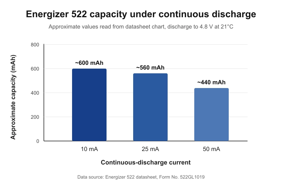
A fresh PP3 may spin a very small or lightly loaded motor briefly. Under a larger startup demand, its terminal voltage can fall sharply, the driver may enter undervoltage lockout, and the motor may stop or repeatedly restart. Use a current-capable regulated 9V supply or a battery pack designed for the required discharge current when evaluating a 12V BLDC system.
The load requires more starting torque than the system can produce
Gear friction, pump pressure, fan inertia, seals, and cold lubricant can raise the starting demand. At 9V, the driver may reach its available voltage or current limit before the motor accelerates through the difficult part of the startup.
Sensorless BLDC control adds another variable. Back-EMF is weak at zero and very low speed, so the controller needs a dedicated startup method before it can commutate from measured back-EMF. A lower supply and a heavier load can reduce the margin of that startup sequence.
Will 9V damage a 12V brushless motor?
Not normally from voltage alone. Nine volts is lower electrical stress than 12V for the winding insulation and power stage. The real risks appear when the complete system operates outside its intended conditions.
Watch for these failure modes:
- the controller behaves unpredictably below its documented input range;
- the motor stalls while significant current continues to flow;
- repeated restart attempts heat the windings or driver;
- an undersized battery or power adapter overheats;
- the lower speed reduces cooling while the load still demands substantial torque;
- the application no longer meets its safety, timing, airflow, or control requirements.
So the useful answer is not "9V is safe" or "9V will burn it." The useful answer is: 9V can be acceptable only after the driver range, current, temperature, startup, and application output have been checked.
A real 12V product example: why the current rating matters
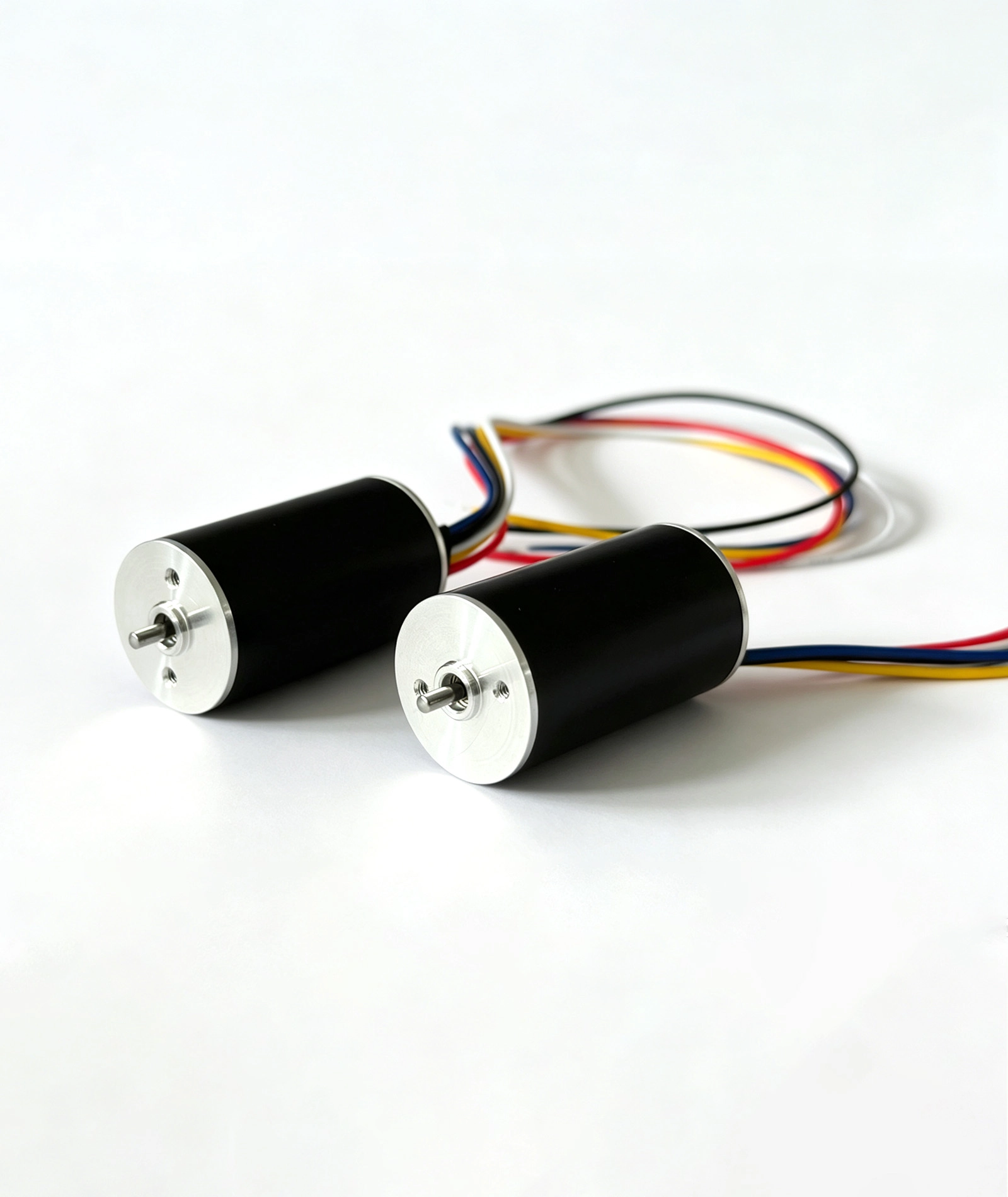
EURARI's EC2035012 brushless DC motor is listed at a nominal 12V. Its published 12V data includes:
| Published parameter | Value |
|---|---|
| No-load speed | 7,000 rpm |
| No-load current | 0.03 A |
| Nominal speed | 6,000 rpm |
| Nominal torque | 125 gf·cm |
| Nominal current | 0.9 A |
| Nominal power | 11 W |
| Stall current | 6 A |
Because 12V × 0.9A = 10.8W, the listed 11W is consistent with nominal electrical input power rounded to the nearest watt. The product page does not identify it as shaft output power, so it should not be used as a mechanical-output figure without an efficiency measurement.
What two 12V samples showed
EURARI supplied a sample sheet dated August 20, 2026 for two 12V motors from the 2035 series. The recorded no-load results were:
| 12V sample | No-load speed | No-load current |
|---|---|---|
| Sample 1 | 7,014 rpm | 0.05 A |
| Sample 2 | 6,960 rpm | 0.07 A |
Both measured speeds are close to the 7,000 rpm no-load value published for the EC2035012. The current readings are worth a closer look, because they show a problem that this article keeps returning to: the same quantity can read differently depending on how it was measured.
No-load current for a motor of this size is only a few tens of milliamps, and at that level the accuracy of the supply's own current display matters. These two samples were recorded on a general-purpose bench supply. The comparison shown earlier used a higher-accuracy supply and read 0.027A at 12.01V. EURARI's published specification is 0.03 A, consistent with the higher-accuracy reading and rounded upward for batch variation.
The practical lesson is not that one of these readings is fake. It is that a small-current figure is only meaningful with the instrument and conditions attached, which is exactly what you should ask of any supplier's data — including ours.
The same sheet records one loaded point at 4,908 rpm and 0.33 A with a stated load value of 50 g. Because the sheet does not define the complete fixture or provide a torque unit beyond that notation, this point should be treated as a sample-specific test condition rather than a rated torque value.
These figures do not predict the motor's 9V performance. They show why the power source cannot be selected by voltage alone. A source that can sustain the motor's working current and startup transient is fundamentally different from a small battery that quickly sags under load.
The example also shows why a 9V test should not reuse the 12V stall-current value as if it were a measured 9V result. A new voltage, controller, and load require a new operating-point measurement.
For other frame sizes and winding options, see EURARI's brushless DC motor range. Individual product data should be treated as the nominal reference, not as approval for an unspecified lower-voltage operating point.
Is 9V at full duty the same as 12V at 75% PWM?
Not always.
Both cases can produce a similar average applied voltage under some conditions, but the system still sees different bus voltages. That difference can affect:
- driver undervoltage thresholds;
- the voltage headroom available for current control;
- current ripple and switching behavior;
- startup and fault handling;
- the achievable torque at higher speed.
Portescap's BLDC PWM guidance emphasizes that torque follows average current, while current ripple and PWM behavior depend on the motor inductance, resistance, supply, switching frequency, and duty cycle. A simple duty-cycle calculation is therefore useful for estimation, not proof that two operating conditions are equivalent.
How to test a 12V BLDC system at 9V
Use a controlled test instead of connecting an unknown battery and judging only by whether the shaft turns.
- Identify the system architecture. Record the motor model, winding, Hall or sensorless configuration, driver model, firmware, and whether the driver is internal or external.
- Check the documented voltage ranges. Confirm that 9V is inside the driver's operating range, not merely above its absolute lowest threshold.
- Use a current-limited bench supply. Set a conservative current limit based on the motor and driver documentation. Do not use the published stall current as the default continuous limit.
- Measure voltage at the driver input. Supply-cable and connector drops can make the controller see less than the supply display shows.
- Test no-load startup first. Record startup behavior, no-load speed, and current.
- Find the startup and hold thresholds. Reduce the supply in small steps to find the lowest voltage that starts the motor from standstill, then repeat from a running state to find the lowest voltage that keeps it turning. The two are not the same number.
- Add the real load progressively. Measure speed, current, output, and winding or housing temperature at the intended duty cycle.
- Repeat at worst-case conditions. Include cold starts, maximum mechanical load, minimum expected source voltage, and any restrictive cooling condition.
- Define pass criteria before the test. Examples include startup success, minimum rpm, maximum current, temperature rise, noise, airflow, cycle time, and fault-free operation.
If the application is commercial or safety-relevant, ask the motor and driver supplier to review the intended 9V operating point. EURARI provides motor selection and engineering support for applications that require a winding, driver, or performance target outside the published nominal point.
Practical decision table
| Situation | Likely result at 9V | What to verify |
|---|---|---|
| Regulated 9V supply, driver rated for 9V, light load | Often runs at lower maximum speed | Startup, rpm, current, temperature |
| Small rectangular 9V battery | Voltage may sag or the motor may not start | Loaded voltage and source-current capability |
| Driver minimum input is above 9V | No start or controlled shutdown | Driver datasheet and UVLO thresholds |
| Heavy starting load | Slow start, failed start, or repeated restart | Starting current, acceleration, driver faults |
| Constant-torque load | Current may remain substantial while speed falls | Continuous current and thermal rise |
| Fan or blower load | Lower speed usually reduces the mechanical load | Actual airflow, pressure, current, cooling |
| Speed-critical or certified product | A simple substitution is not acceptable | Full system revalidation |
So, can a 12V BLDC motor run on 9V?
A 12V BLDC motor can sometimes run on 9V without damage, but the result is system-specific. Expect a lower speed ceiling and less available power. Do not assume a fixed torque reduction, and do not assume that every 9V source can supply the required current.
In EURARI's documented no-load comparison, the sample ran at 7,068 rpm at 12.01V and 5,278 rpm at 9.01V, and both tested units started reliably at 9V with no load. That confirms operation for the tested samples and setup, not every 12V BLDC system.
The fastest reliable check is to answer four questions:
- Does the BLDC driver officially operate at 9V?
- Can the source maintain 9V during startup and peak load?
- Can the motor start and meet the required speed, torque, or airflow at 9V?
- Do current and temperature remain within approved limits over the real duty cycle?
If any answer is unknown, treat 9V as a test condition, not an approved operating voltage.
Frequently asked questions
Can a 12V BLDC motor run directly from a 9V battery?
Only if the motor has a compatible controller and the battery can supply the startup and running current. A bare three-phase BLDC motor cannot be connected directly to a battery without electronic commutation. A small rectangular 9V battery may also sag under motor load even when it reads close to 9V with no load.
Will a 12V motor run 25% slower at 9V?
It may be a useful first estimate for a lightly loaded motor, but it is not guaranteed. EURARI's sample measured 7,068 rpm at 12.01V and 5,278 rpm at 9.01V. The 9V result was 28 rpm, or about 0.5%, above the 5,250 rpm voltage-ratio estimate based on the published 7,000 rpm no-load speed. Driver losses, PWM control, winding resistance, current limits, and the load affect the result.
What is the lowest voltage a 12V BLDC motor will run at?
There are two different answers, and the starting one is higher. On the EC2035012 units tested for this article, the no-load startup threshold was about 7.09 V, while a motor already running kept turning down to about 6.08 V. Both are no-load figures; a real load raises the startup threshold. Any product decision should use the supplier's documented minimum startup and minimum operating voltages, measured under the actual load.
Does lower voltage reduce BLDC motor torque?
Torque is primarily proportional to motor current. Lower voltage reduces the driver's ability to maintain that current as speed and back-EMF rise, so the torque-speed envelope becomes smaller. Low-speed torque may remain available if the driver can still regulate the required current.
Can undervoltage overheat a brushless motor?
Undervoltage by itself does not automatically increase motor current or heat. Overheating can occur if the motor stalls, repeatedly restarts, loses cooling, or continues to carry a high-torque load with substantial current.
Why does the motor run from a bench supply but not a 9V battery?
The two sources may have very different current capability and internal resistance. The battery voltage can collapse during startup, which may trigger the controller's undervoltage protection or leave the motor without enough accelerating torque.
Should I use a boost converter to raise 9V to 12V?
A boost converter can provide a 12V bus only if its input source, output-current rating, transient response, efficiency, and thermal design are adequate. It does not create free power. The 9V source must supply more input current than the 12V load current after conversion losses are included.
Reference sources
- EURARI. Brushless DC Motors. Accessed August 18, 2026.
- EURARI. EC2035012 Brushless DC Motor Ø20mm BLDC 12V EC Motor. Accessed August 18, 2026.
- Texas Instruments. Low-Voltage Motor Drive Operation with a Smart Gate Driver. Application Report SLVAE64, December 2018.
- Portescap. Understanding the Effect of PWM When Controlling a Brushless DC Motor. Accessed August 18, 2026.
- Energizer. Energizer 522 9V Product Datasheet. Form No. 522GL1019. Accessed August 18, 2026.
