


Why Coreless Motors Cost More — and When They're Worth It
Coreless motors usually cost more because a conventional iron-supported armature is replaced by a precisely formed, bonded, self-supporting winding that is harder to manufacture.
In a brushed coreless motor, removing the laminated iron armature reduces rotor inertia and eliminates armature iron loss and tooth-related cogging. In a slotless BLDC motor, removing stator teeth eliminates tooth-related cogging and reduces tooth-related iron loss, but it does not automatically reduce rotor inertia; back iron can still saturate and dissipate energy. These changes can improve acceleration, low-speed smoothness, control response, and efficiency at the intended operating point. They do not make every coreless motor stronger, cooler, longer-lived, or less expensive at system level.
In this guide, better means better for applications that value fast starts and reversals, smooth motion, compact size, low moving mass, or reduced iron loss. An iron-core motor can still be the better choice for low unit cost, high continuous torque, thermal overload capacity, a simple drive, or a mechanically severe environment.
Key takeaways
- The price premium pays for winding precision, bonding, magnetic design, balancing, and quality control rather than for a larger quantity of material.
- In a brushed coreless motor, the rotating armature is a light self-supporting copper coil. In a brushless design, the comparable construction is usually a slotless or ironless-winding stator with a permanent-magnet rotor.
- The clearest benefits are low rotor inertia in brushed coreless designs, no tooth-related cogging, low iron loss, and fast current response.
- Low inductance and low thermal mass also create design obligations. PWM current ripple, winding temperature, continuous current, and mounting conditions must be checked.
- Compare continuous torque, thermal resistance, inertia, motor constant, inductance, controller compatibility, and duty cycle. Stall torque and no-load speed alone do not establish the better motor.
What coreless actually means
The word coreless describes the active winding structure, not every material inside the motor. In a conventional brushed permanent-magnet DC motor, copper wire is wound around a laminated iron armature. In a brushed coreless motor, the rotating armature is a hollow, self-supporting copper winding fixed to the shaft and commutator. The central magnet, steel housing, shaft, bearings, and magnetic return path can still contain metal or iron.
Several names appear in catalogs. Ironless, hollow-cup, bell armature, and coreless commonly describe a brushed rotor winding without a laminated iron armature. In a brushless DC motor, the winding is stationary and the permanent magnet rotates. Manufacturers often call the related topology slotless or ironless-winding because the coil is not inserted into toothed stator slots. A slotless BLDC motor may still use a cylindrical iron back structure, so the exact cross-section matters more than the label.
Coreless and brushless therefore answer different questions. Coreless or iron-core describes the magnetic and winding construction. Brushed or brushless describes how current is commutated. A buyer can specify a brushed coreless motor or a brushless motor with a slotless, ironless winding.
Why removing iron can improve motion
An iron core is useful because it concentrates magnetic flux and gives a conventional winding strong mechanical and thermal support. It also adds rotating mass in a brushed motor, introduces magnetic teeth or preferred rotor positions, stores magnetic energy, and experiences hysteresis and eddy-current loss when its magnetization changes. A coreless design removes those penalties from the active armature or slot region while retaining a permanent-magnet field and a magnetic return path elsewhere in the assembly.
The copper conductors still interact with the air-gap magnetic field and generate torque. A brushed coreless motor does not need iron inside its moving coil to produce torque; in a slotless BLDC motor, the winding is stationary and interacts with the rotating permanent-magnet field. The engineering challenge is to create enough useful flux across a larger effective air gap while keeping the winding mechanically stable, concentric, electrically insulated, and thermally safe. High-performance magnetic materials and careful geometry can compensate for some of the flux that an iron-toothed structure would otherwise concentrate.
This is why the missing iron is neither free nor automatically beneficial. The designer exchanges a simple supported winding and concentrated magnetic path for a precision coil, a different air-gap design, and tighter control of the complete electromechanical system.
Why coreless motors cost more to manufacture
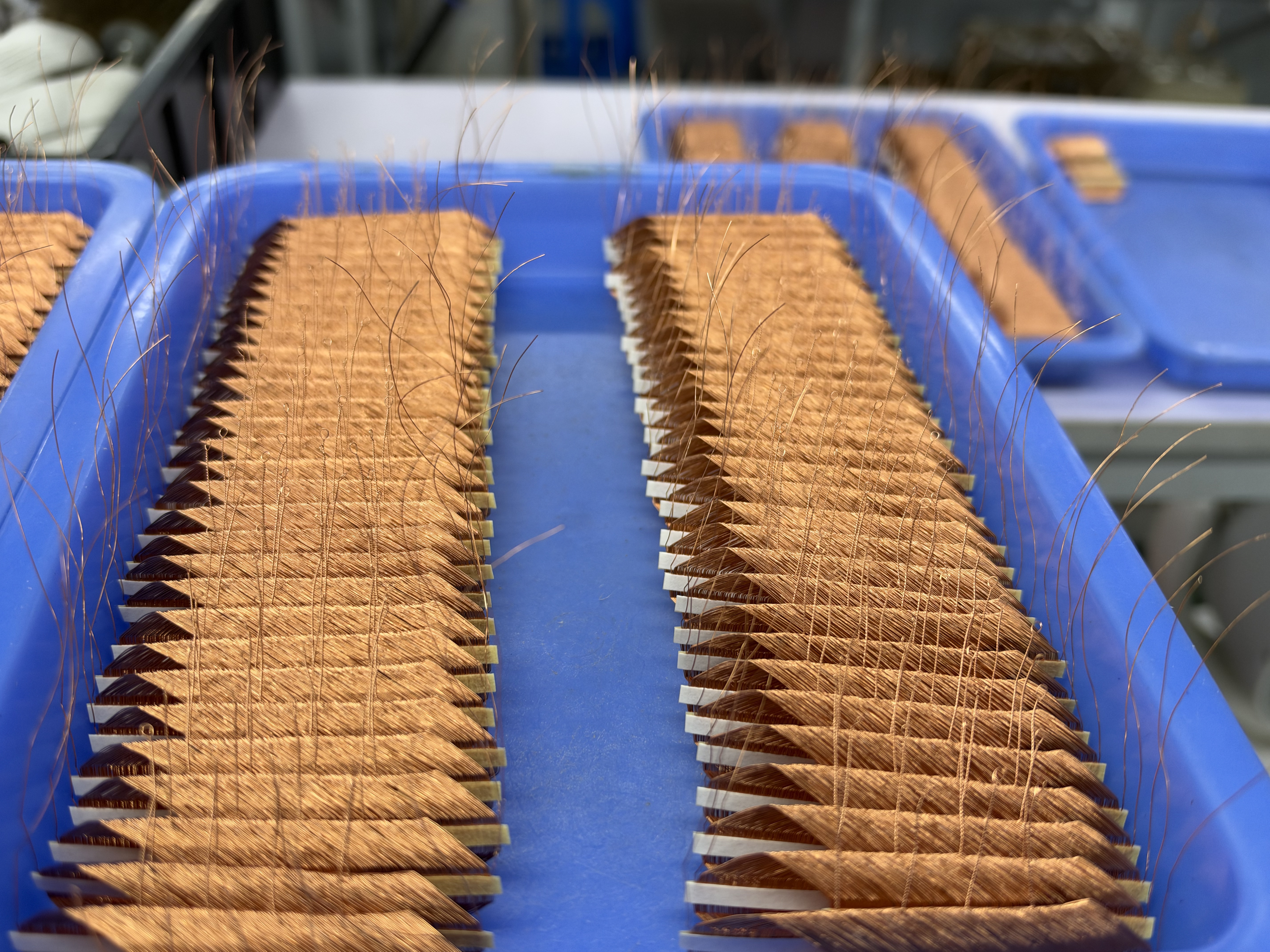
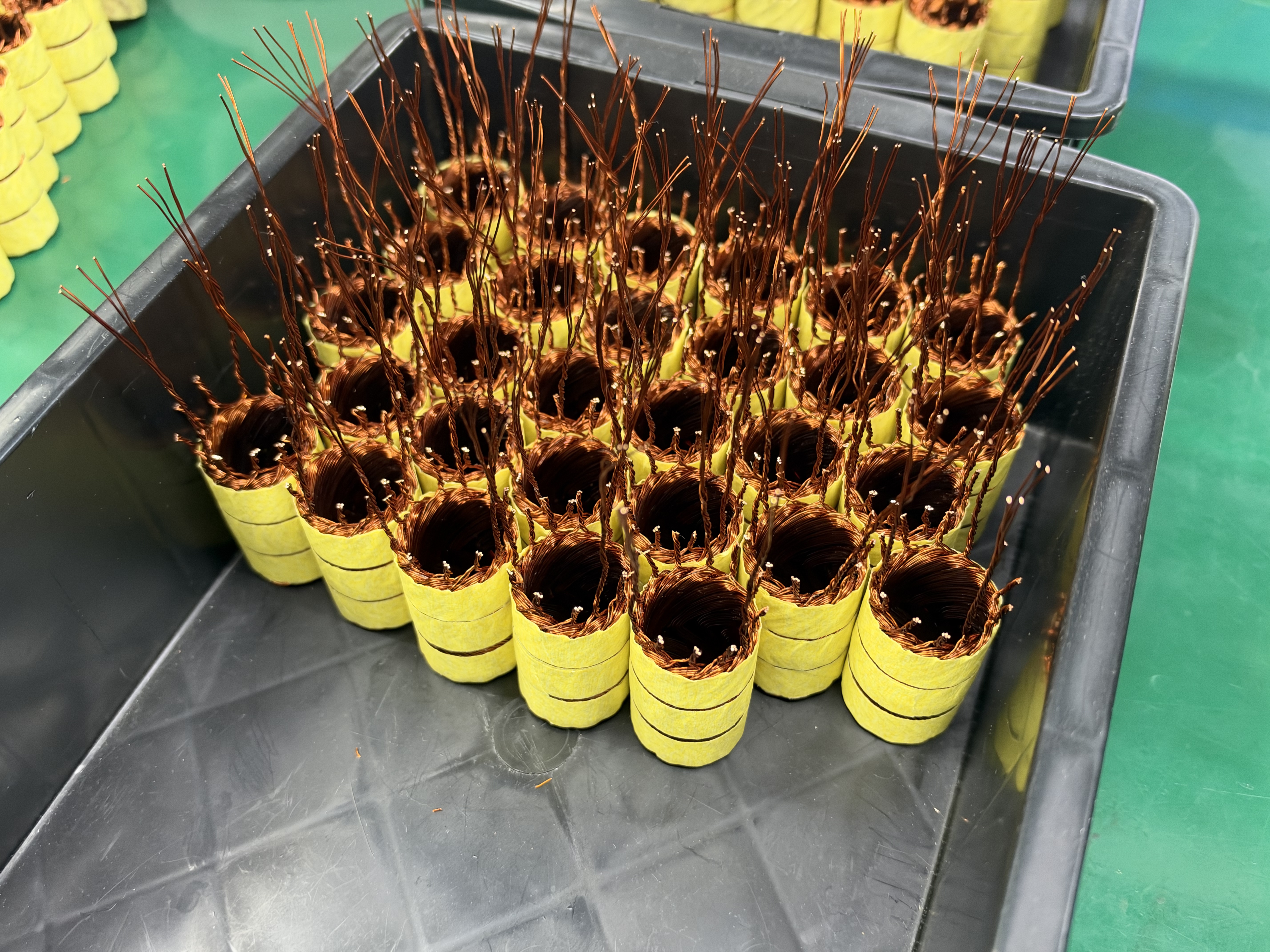
A conventional iron armature or slotted stator provides a ready-made structure around which wire can be wound or inserted. Many brushed coreless and slotless windings are formed on a mandrel and then bonded or encapsulated; unlike a slotted winding, they cannot rely on iron teeth to locate and support the conductors. The wire pattern, adhesive system, curing cycle, wall thickness, roundness, lead termination, and bond to the commutator or stator must all be controlled precisely.
- Form the winding accurately. Fine enamelled wire is laid in a skewed, basket, rhombic, or segment pattern so the final coil produces the intended torque constant and resistance.
- Bond and stabilize the coil. Heat and pressure can fuse a bonding layer on adjacent wires; tape, glass fibre, resin, or overmoulding may add stiffness where the design requires it.
- Join the winding without distorting it. Brushed designs require reliable connections to commutator segments. Brushless designs require accurate phase connections, sensor alignment, and stator integration.
- Control concentricity and balance. A thin cylindrical winding that runs at high speed must remain round, centred, and mechanically secure. Small geometric errors can become vibration, rub, acoustic noise, or local heating.
- Validate the complete motor. Resistance, inductance, back EMF, no-load current, vibration, direction, sensor timing, dielectric integrity, and thermal behaviour may all require inspection or testing.
Premium designs may also use high-energy magnets, precision bearings, low-resistance commutation materials, specialised controllers, or tighter balancing grades. These are common cost drivers, but none is part of the definition of coreless. Order volume, customization, qualification, and the required operating environment can change unit cost as much as the topology itself.
What the extra cost buys
Faster starts, stops, and reversals
For a brushed coreless motor, removing the laminated iron rotor can reduce the motor's rotating inertia substantially. Angular acceleration depends on net torque divided by total inertia, including the motor, coupling, gearbox, and load reflected to the motor shaft. A lighter motor rotor therefore produces a real advantage when rotor inertia is a meaningful part of the total. The gain becomes smaller when reflected load inertia or transmission-component inertia and friction dominate the system. Calculate load inertia at the motor shaft using the actual transmission ratio; an ideal reduction gearbox reduces reflected external-load inertia by the square of that ratio.
This low-inertia claim should not be transferred automatically to every slotless BLDC design. A brushless motor rotates a permanent magnet, and some slotless constructions use a larger magnet to compensate for the magnetic gap. The actual rotor inertia in the datasheet is the deciding value.
Smoother low-speed motion
A toothed iron structure creates preferred magnetic positions even when the motor is unpowered. The resisting torque between those positions is cogging or detent torque. Removing the teeth removes that tooth-slot reluctance variation, allowing the shaft to move without the same magnetic stepping feel. The result can be smoother low-speed control, more predictable small position changes, and less excitation of mechanical vibration.
No cogging does not mean zero torque ripple. Brushed commutation, BLDC block commutation, Hall-sensor placement, winding asymmetry, current ripple, and manufacturing tolerances can still modulate torque. Sinusoidal commutation or field-oriented control can reduce commutation ripple in a BLDC system, but it does not turn a real motor into an ideal torque source.
Lower iron loss at speed
When a conventional active iron core is repeatedly magnetized, it dissipates hysteresis and eddy-current energy. A brushed coreless rotor removes those rotor iron losses. Slotless BLDC construction can also reduce tooth-related iron loss. This can lower no-load current and improve efficiency, especially where speed makes iron loss important. Copper loss, brush contact loss, bearing friction, windage, magnet or back-iron eddy currents, and controller loss still remain.
Fast electrical response
Ironless windings usually have lower inductance and a shorter electrical time constant. Current can change quickly, which lets torque respond quickly to a current command. That supports high-bandwidth servo control and rapid changes in load. The same property makes the winding more sensitive to PWM switching. If the drive voltage, switching frequency, current loop, and motor inductance are poorly matched, current ripple can raise RMS current, acoustic noise, and winding temperature; in brushed motors it can also accelerate commutator and brush erosion.
More linear torque control
In a brushed coreless motor, removing the iron armature avoids armature saturation and helps preserve a nearly linear torque-current relationship over the intended operating range. The usable relationship is still bounded by commutation, temperature, magnet, and magnetic-return-path limits. In a slotless BLDC motor, the remaining back iron, magnet operating point, rotor position, and control strategy also set the linear range. Iron-core motors are approximately linear through much of their normal range, so this practical advantage matters most in precise control and high-current edge cases rather than in every general-purpose drive.
Efficiency, power, and torque are different questions
A motor can accelerate quickly without producing more continuous torque. Low inertia reduces the torque required to accelerate the motor's own rotor; it does not increase the steady torque available to the load. Likewise, a high no-load speed does not prove high power, and a large stall torque does not prove that the motor can deliver that torque continuously. Stall current heats the winding rapidly and is normally a transient boundary, not a rated operating point.
Efficiency is mechanical output power divided by electrical input power at a stated speed and torque. Removing active iron loss can improve the result, but copper loss rises with the square of current. At a high-torque operating point, winding resistance and thermal resistance may dominate. A coreless motor can be more efficient at the target duty point, yet an iron-core or slotted motor with a shorter magnetic gap and better heat path can deliver more continuous torque in the same envelope.
Power density and torque density also depend on magnet grade, copper fill, winding geometry, housing, cooling, commutation, speed, and the manufacturer's allowable temperature rise. The useful comparison is a matched operating point on each motor's torque-speed curve, checked against the continuous operating range and thermal model.
Engineering trade-offs of removing the core
| Design issue | What improves | What must be managed |
|---|---|---|
| Rotor and magnetic inertia | Fast dynamic response in brushed coreless designs | Total reflected load inertia still controls system acceleration; verify actual BLDC rotor inertia |
| Cogging | No tooth-related preferred rotor positions | Commutation, PWM, Hall alignment, and winding tolerances can still create torque ripple |
| Iron loss | Lower hysteresis and eddy-current loss in the removed active iron | Copper, bearing, commutation, windage, magnet, back-iron, and controller losses remain |
| Inductance | Short electrical time constant and fast current response | PWM ripple and control-loop stability may require a suitable controller or added inductance |
| Thermal behaviour | Lower heat generation from the removed active-iron losses | The winding has limited thermal mass; heat may cross an air gap before reaching the housing |
| Magnetic circuit | No tooth saturation and smooth air-gap field | A larger effective gap can reduce flux density and may require a stronger magnet or more copper |
| Mechanical construction | Compact coil with no iron armature | The coil must remain bonded, concentric, balanced, and secure across speed and temperature |
Thermal design deserves special attention. In a brushed coreless motor, heat generated in the rotating coil is dissipated to the stationary structure through several paths, including the thermally resistive air gap. The winding can heat faster than the housing, so case temperature alone may not reveal the peak coil temperature during a short overload. A brushless slotless motor can have a better path because its winding is stationary, but the actual winding-to-housing thermal resistance and mounting surface still decide continuous current.
Coreless brushed and coreless brushless are not the same
| Selection point | Brushed coreless DC | Slotless or ironless-winding BLDC |
|---|---|---|
| Current switching | Mechanical brushes and commutator | Electronic commutation from Hall sensors, encoder feedback, or sensorless estimation |
| Moving element | Self-supporting copper armature rotates | Permanent-magnet rotor rotates while the winding remains stationary |
| Main dynamic benefit | Very low rotor inertia is common | No detent torque and strong high-speed capability; rotor inertia must be checked |
| Life-limiting elements | Brushes, commutator, bearings, and winding temperature | Bearings, electronics, insulation, sensors, and winding temperature |
| Drive complexity | Can run from a DC supply; speed or torque control may add electronics | Requires a compatible electronic commutator and often tuning or feedback |
| Typical reason to choose | Simple compact drive with fast response and low starting voltage | Long operating life, high speed, low cogging, or controlled servo motion |
This distinction explains why the word coreless alone cannot predict service life. A brushed coreless motor still has wearing electrical contacts. A brushless ironless-winding motor removes that contact mechanism, but its life is still conditional on bearing load, speed, vibration, temperature, contamination, and the controller.
Coreless and iron-core motors by duty cycle
| Requirement | Coreless or slotless advantage | When iron-core or slotted may be better |
|---|---|---|
| Rapid start, stop, or reversal | Low moving inertia and fast current response can shorten transients | A heavy external load makes rotor inertia less important |
| Very smooth low-speed motion | No tooth-related cogging improves small moves and speed stability | A geared system with backlash or stiction may dominate the motion error |
| Battery-powered operation | Reduced iron loss and low no-load current can preserve energy | A lower-cost motor may be adequate if duty is short and current is modest |
| High continuous torque | Possible in a well-cooled design sized for the load | Slotted iron-core construction often provides better flux concentration and heat conduction |
| Repeated peak torque | Short time constant can deliver quick torque response | Low thermal mass and bonding temperature may limit repeated overload |
| Lowest purchase price | Can pay back only when system size, control, or energy use has value | Mass-produced iron-core construction is normally easier and less expensive |
| Long life at high speed | Brushless slotless construction avoids brush wear and reduces cogging | A brushed coreless motor remains subject to commutator and brush limits |
| Harsh shock, temperature, or contamination | Specialized versions can be qualified | A supported slotted winding may offer a more rugged starting point |
Coreless construction is worth its premium when the application makes dynamic response, smoothness, size, mass, high-speed loss, or control quality economically important. Typical candidates include precision pumps, miniature robotic joints, optical mechanisms, grippers, portable instruments, aerospace actuators, medical hand tools, and compact automation. It is not a status upgrade for a steady fan, conveyor, or actuator whose real constraints are purchase price and continuous shaft torque.
How to compare datasheets before buying
Start with a defined operating point rather than a preferred topology. State the supply, controller, target speed, continuous and peak torque, motion profile, ambient temperature, available mounting surface, radial and axial shaft load, life target, allowable noise, and package envelope. Then compare motors at the same conditions.
- Use continuous torque and continuous current as the first boundary. Treat stall torque and stall current as transient values unless the manufacturer provides a safe pulse duration and starting temperature.
- Check rotor inertia and mechanical time constant. Estimate the load inertia reflected through the gearbox so the expected acceleration is based on the complete system.
- Compare torque constant, speed constant, winding resistance, and motor constant. Different windings can trade voltage, current, resistance, speed constant, and torque constant within the same motor platform, but winding-specific thermal, speed, and current limits must still be checked.
- Review inductance and the controller's PWM strategy. Confirm switching frequency, bus voltage, current-loop bandwidth, current ripple, and whether an external choke is required.
- Model winding temperature. Use winding-to-housing and housing-to-ambient thermal resistance, thermal time constants, mounting conditions, and the stated maximum winding temperature.
- Separate motor life from topology. Specify brushes or brushless commutation, bearing type, speed, duty cycle, start-stop and reversing frequency, vibration, contamination, and required qualification evidence.
- Validate the assembled mechanism. Measure speed, current, torque, winding or inferred coil temperature, vibration, acoustic behaviour, and control stability with the actual gearbox, load, controller, and enclosure.
EURARI's motor selection guide asks for supply and current limits, PWM or control requirements, encoder needs, duty cycle, environment, and dimensional restrictions. Those inputs are the minimum needed for a useful motor comparison.
Two EURARI examples show why the label is not enough
EURARI currently offers over 60 coreless motor models, covering both the brushed DCL series and the brushless ECL series. The range includes multiple motor diameters, voltage options, and performance configurations for different application requirements. Custom windings and selected mechanical or electrical configurations are also available for project-specific needs.
The two examples below are not a direct performance comparison, because their frames, voltages, commutation, and rated points differ. They show why buyers should specify both winding construction and commutation type before comparing price or life.
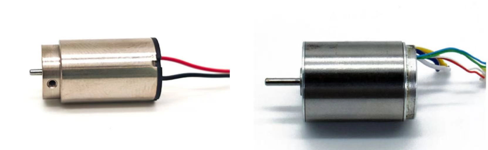
| Published item | DCL10207.4 | ECL1620024 |
|---|---|---|
| Motor type | Brushed coreless DC | Coreless BLDC |
| Nominal voltage | 7.4 V DC | 24 V DC |
| Frame | 10 mm diameter × 20 mm housing | 16 mm diameter × 20 mm housing |
| Published nominal point | 11,500 rpm, 15 gf·cm, 1.8 W (shaft output) | 12,700 rpm, 17.5 gf·cm, 3 W (electrical input, measured with driver) |
| Published typical life | 1,500 hours | 5,000 hours |
| What to confirm | Brush grade, duty, bearing load, start-stop frequency, test conditions | Controller, Hall or sensorless scheme, PWM, bearing load, thermal mounting, test conditions |
Note the two power figures. The DCL10207.4 value is shaft output: 15 gf·cm at 11,500 rpm works out to about 1.8 W of mechanical power. The ECL1620024 value is measured electrical input at the supply, with the driver board in circuit; the same torque and speed correspond to about 2.3 W of mechanical output, so the difference is driver and motor loss at that point. Neither figure is wrong, but they are not the same quantity — which is the point of this guide. Values are EURARI product-page data as of 17 September 2026; request the current datasheet and test conditions before design release.
Frequently asked questions about coreless motors
Does coreless mean there is no iron anywhere?
No. It normally means the active armature or winding is not built around the conventional laminated, toothed iron core. A steel housing or stationary return path can still carry magnetic flux, and the shaft and bearings are still metallic. For BLDC products, verify whether the manufacturer means slotless, ironless-winding, or a fully ironless stator topology.
Are coreless motors always more efficient?
No. Removing active iron loss can improve efficiency and no-load current, especially at speed, but total efficiency depends on the operating point. Copper loss, brushes, bearings, windage, magnets, back iron, and the controller still dissipate power. Compare measured or calculated efficiency at the required speed and torque.
Do coreless motors produce more torque?
Not automatically. A coreless motor can have an excellent torque-to-inertia or power-to-weight ratio, but low inertia is a dynamic advantage rather than a guarantee of higher continuous torque. Iron-core or slotted motors can use a smaller magnetic gap and a better heat path, which can support more continuous torque in some envelopes.
Why can low inductance be a problem?
Low inductance lets current and torque respond quickly, but it also allows more current ripple under PWM. Excess ripple increases RMS current and heating and can stress brushes or destabilize a fast current loop. Confirm the controller's switching frequency and current regulation, and add inductance only when the motor and controller suppliers support it.
Do coreless motors overheat more easily?
They can heat quickly during overload because the winding has low thermal mass, and a rotating coreless coil transfers heat across an air gap. That does not mean every coreless motor runs hotter in normal service. Use the selected motor's thermal resistance, time constants, maximum winding temperature, mounting surface, airflow, and actual RMS current.
Is a coreless motor the same as a brushless motor?
No. Coreless describes the winding or magnetic structure; brushless describes electronic commutation. Coreless brushed motors and slotless or ironless-winding BLDC motors are both available. State both attributes in an RFQ so the supplier does not infer the wrong topology.
When is the price premium worth paying?
Pay the premium when lower inertia, smoother low-speed motion, lower iron loss, smaller size, lower moving mass, or control bandwidth changes the value of the finished system. If the load runs steadily and is limited mainly by continuous torque, temperature, shock, or purchase price, compare an iron-core motor on equal duty before choosing coreless.
Final recommendation
Coreless motors often cost more because precision winding and assembly replace the mechanical support supplied by a simple iron core. The performance gain is real, but specific: faster dynamic response in brushed coreless designs, smoother motion without tooth-related cogging, lower active iron loss, and rapid electrical response. Each benefit comes with conditions involving total inertia, PWM, thermal resistance, continuous current, commutation, and manufacturing quality.
Choose coreless when those conditions improve the product that the customer experiences or the system that the engineer must control. Choose iron-core when continuous load capability, ruggedness, thermal margin, or unit price matters more. The right question is not whether coreless is generally better. It is whether its dynamic and loss advantages solve a requirement that can be measured in the real assembly.
To request a matched recommendation, send EURARI your supply voltage and current limits, target speed and torque, duty cycle, ambient conditions, available envelope, shaft loads, controller or PWM method, feedback requirement, and life target. Review the EURARI coreless motor technical note, explore the brushless DC motor range or brushed DC motor range, and contact EURARI for the current datasheet, a sample, or an OEM quotation.
Technical sources
Sources checked 17 September 2026.
- Portescap — Brushed DC Motor Basics. Construction, equations, self-supporting ironless rotor, cogging, and iron loss.
- maxon Academy — Permanent Magnet DC Motor with Coreless Winding. Coreless magnetic circuit, inertia, losses, low inductance, winding manufacture, and PWM cautions.
- FAULHABER — Winding Technology. Self-supporting skew-wound construction and the role of winding precision.
- FAULHABER — DC Micromotors Technical Information. Coreless terminology, cogging-free operation, dynamics, and product-specific performance context.
- Portescap — Drivers for Ironless Rotor DC Motors. Low inductance, short electrical time constant, servo behaviour, and drive requirements.
- Portescap — Understanding the Thermal Parameters of Coreless DC Motors. Coil heating, thermal resistance, thermal capacitance, and motor selection.
- Portescap — Slotless vs Slotted Brushless DC Motor Design. BLDC construction, cogging, inductance, thermal sensitivity, and application boundaries.
- maxon — Cogging Torque and Ripple Torque. Distinction between magnetic cogging and commutation-related torque ripple.
- maxon — Motor Data and Simulation. Torque constant, linearity, and interpretation of motor data.
- EURARI — Motor Selection Guide. Supply, control, encoder, duty-cycle, environment, and dimensional inputs for selection.
- EURARI — DCL10207.4 Product Page. Model-specific brushed coreless specifications used in the example.
- EURARI — ECL1620024 Product Page. Model-specific coreless BLDC specifications and product image used in the example.
